Bauer: how to adjust S715XL meter
WARNING: doing this without indepth knowledge of this camera, its electronic and precision measurement tools e.g. for lightmeter adjustment and others, gives unpredictible results and may harm your camera!
The Bauer S 715 XL Microcomputer exposure meter can be adjusted by turning an internal potentiometer.
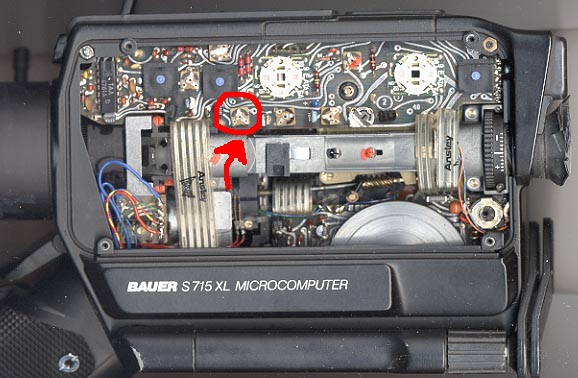
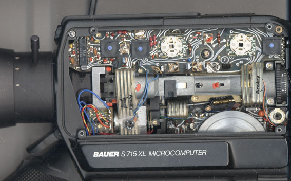
Begin by removing the port side cover of the camera by removing four small Phillips head screws that hold the cover in place. Opening up the camera, you see the innards as shown. Beware the small black plastic film footage counter cam lever; it is held in place by friction and can be easily lost if you turn the camera so that the open side is down (cam lever is removed in the photo).
The picture below shows which potentiometer controls the sensitivity of the exposure meter.
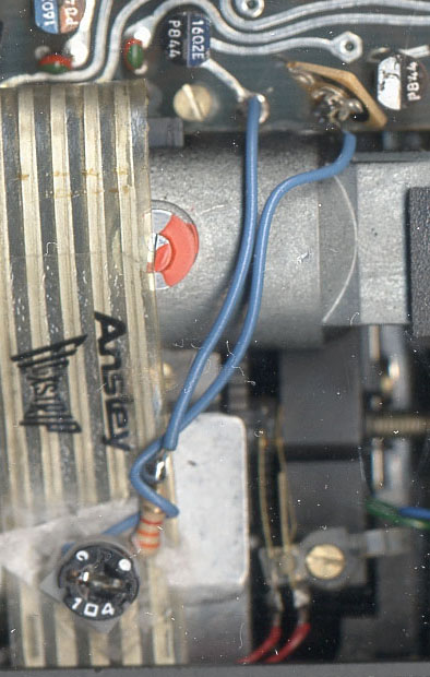
The stock exposure adjustment part is a 50kOhm trimpot, and is clearly not designed for multiple tweakings. If you're planning on modifying your Bauer for lightmeter exposure compensation, you'll want to replace that cheap pot with a somewhat sturdier 100kOhm part, such as a Clarostat or Bourns (in the USA you can buy at the counter at Radio Shack, or mail order through DigiKey). Note that only 2 leads are used: the wiper and one end lead (I soldered the wiper and third leads together). Wire a ~5kOhm resistor in series with it, because when the trimpot is turned all the way counterclockwise, the stock exposure circuit appears to compensate down to 0 ASA - not very useful. On the other end, the modified circuit appears to have about +2/- 3 stops leeway, so E64T should easily fall into the range of adjustment. Given the 40/160 switch is working, the total usable range of film stocks is now from ASA 6 to 640. The only problem may be with 500 ASA Vision 2 negative stock if it has no cartridge notch to accept the Bauer's faster 160 switch setting. Then you'd have to "customize" the cartridge or use manual exposure adjustment.
I left one lead of the existing potentiometer in place, as it is soldered to a hole in the double sided circuit board which is not plated thru. This way, if some future camera repairman wants to return it to spec he can remove my mod and resolder the original part in place.
I superglued the new pot/resistor circuit to a flexible circuit, leaving the remaining area clear for inspection and maintenance.
I drilled a ~ 3/16" hole through the metal side plate to fit a small flat blade screwdriver. Be careful to avoid getting metal flakes in the camera.
(Instructions and pictures courtesy of Bob Hughes - Dec. 2005)


